 Andrew Lundberg
- Guides
- Posted
The PH+ guide to thermal breaks
Building physics take no prisoners. Anyone designing, constructing or upgrading the thermal envelope of a building to modern energy performance levels is duty bound to understand and minimise thermal bridging, or suffer the consequences. One-man thermal bridging encyclopaedia Andrew Lundberg of Passivate, who teaches thermal bridging analysis at Dublin Institute of Technology, gives some practical advice on why and how to tackle thermal bridging head on, and describes some of the leading innovations in thermally broken components.
This article was originally published in issue 22 of Passive House Plus magazine. Want immediate access to all back issues and exclusive extra content? Click here to subscribe for as little as €10, or click here to receive the next issue free of charge
When it comes to low energy building design, the heat is truly on. In fact, we should really stop talking about low energy building design as if it’s something that will happen in the future, and take on board the fact that we are in the final phases now of implementing the nearly zero energy building (nZEB) standard across Europe, including the UK. Low energy building is basically the new bog standard. In this quagmire of trying to design to reduce heat losses, maintain low U-values despite the need for structural elements, fire resistance, acoustic performance etc., as well as the need to avoid mould growth and condensation, what is the magic bullet?
Well, in short, there are many products which try to play the roles of many in one, commonly referred to as thermal breaks. In some cases, manufacturers of these products have done extensive testing and design already for you, in order to prove their products in multiple common installations, which makes it much easier to specify. In other cases, the need for thermal breaks is brought about from a small number of bespoke junctions which arise due to some aspect of the design which necessitates penetrating the thermal envelope with a structural or aesthetic component.
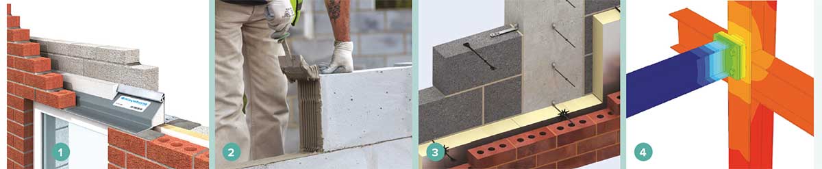
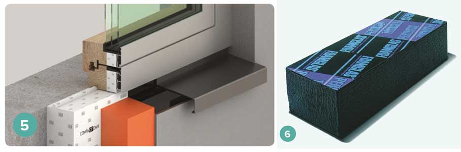
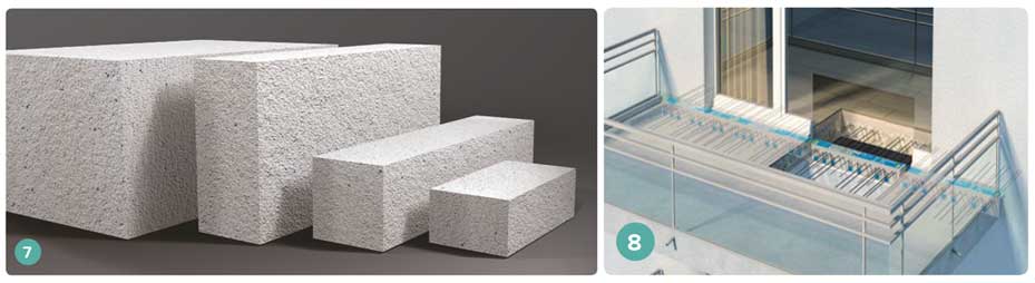
The vastly expanding range of thermal breaks includes 1 Keystone Lintels' Hi-therm lintels; 2 Celcon AAC blocks; 3 TeploTie basalt wall ties; 4 Farrat structural thermal break plates
In these cases, the design and specification of the thermal break takes place by thermal analysis of the junction to determine its additional heat loss and temperature profi le. The thermal analysis results can tell you a lot – and on large-scale projects the inclusion or exclusion of a thermal break can result in many tens of thousands of Euros / Pounds spent or saved – so knowing what to put in and where to put it is crucial.
In the words of Miles Kington – repeated famously by Ireland and England’s favourite ex-rugby player: “Knowledge is knowing a tomato is a fruit. Wisdom is not putting it in a fruit salad”. Materials used to make thermal breaks can consist of anything from high-density EPS (expanded polystyrene), aerated or lightweight concrete, foamed PVC, cellular glass to polyamide / nylon, basalt or rubber, to name but a few. To identify where a thermal bridge occurs, and hence identify which product is best used to reduce its effects, a designer should be able to take a pencil on a full set of construction drawings in plan and section, and run around the primary insulation layer of the entire building without having to lift the pencil to jump across a non-insulating or structural component. Where the pencil needs to be lifted, put on the brakes, zoom in and focus.
In the following section we’ll look at some typical locations for thermal bridges and some products which can be used to improve them.
Linear thermal bridges
When it comes to thermal breaks at linear thermal bridges, we’re talking here more about locations where two building elements meet, be that two or even three or more external building elements, or where internal elements meet external elements such as internal partitions or intermediate floors - and not where linear thermal bridges in planar building elements, such as timber studs in timber framed walls or joists in ceilings – occur. Some of the most common linear thermal bridges occur at junctions in masonry construction, particularly at ground floor connections where the entire leaf, or just the inner leaf, is continuous down to foundation, thus bridging the cavity / external insulation connection to the floor slab insulation. The most common solution to this is the use of a low-density or aerated concrete block lieu of a standard medium density block at the junction.
5 Compacfoam high density insulation blocks; 6 Foamglas Perinsul cellular glass blocks
One important question regarding thermal breaks is where they are best placed. In the case of a standard wall / floor junction, and indeed most junctions, such a block is placed as closely as possible to the ideal line of where the insulation would have continued if it weren’t for the structure that bridges it. In masonry construction, this is normally for two courses below internal floor level. Naturally, the more courses are laid the lower the rate of return for each additional block course in terms of internal surface temperature achieved and additional heat losses (accounted for by linear psi-values). The same rule applies anywhere that a concrete structural leaf breaks the line of insulation, such as at gable wall junctions with roofs insulated at the ceiling line, or inner leafs of parapet walls, where only a thin layer of insulation follows the upstand of the wall above the roof line. Simply put, where structure replaces insulation, that structural component should have the lowest thermal conductivity possible while still satisfying all other requirements of it from a building regulations compliance, cost and practicality perspective.
Several concrete block manufacturers are now promoting blocks designed to reduce thermal bridging, all manufactured in standard concrete block sizes. This means there is practically no re-training or upskilling required by trades who have to install them. These products can be worked on site just like a standard concrete block. These kinds of considerations need to be borne in mind when specifying materials for thermal breaks. The thermal conductivity values for aerated concrete blocks typically ranges from 0.12W/ mK to 0.33W/mK. To give this some context, the thermal conductivity of softwood timbers is typically 0.13W/mK, and hardwoods up to 0.20W/mK. Compressive strengths of these blocks are normally anywhere from 3N/mm2 to 7.5N/mm2.
7 the Quinn Lite range of AAC blocks and 8 Schöck’s Isokorb insulated balcony connectors.
Other thermal breaks which can be used at linear junctions in masonry, pre-cast or in-situ cast concrete structures include Foamglas, a cellular glass product. It has a thermal conductivity of 0.055W/mK. In terms of relative performance, a poorly performing glass wool insulation roll product will typically be at 0.044W/mK, so as thermal breaks go this is quite good. This product however must have absolutely even load spread from the next course above it, ruling out for example the use of hollow block directly above it, and it cannot be tapped or struck with any tool, so care on site is of crucial importance. The compressive strength of these blocks at breaking point is 2.9N/mm2, and with a safety factor used, a load bearing capacity of 1N/mm2 should be used in structural calculations.
Another product range which has been developed primarily to improve thermal bridges around windows and door installations, while of course not being limited to these locations, is the Compacfoam range of products, distributed in Ireland by Partel Ltd. in Galway. These products demonstrate very good thermal conductivity values (typically 0.038W/mK and 0.046W/mK), a range of available high compressive strengths, high resistance to deformation under load, as well as low water absorption properties. This means that they are both very frost resistant and also maintain their thermal properties despite moisture conditions around them.
They are also relatively breathable, being close in molecular structure to an EPS product. They are available as pre-milled profiles or blocks / slabs which can be cut on site. Speaking from personal experience, these products provide a very elegant and simple solution to door threshold details, however if buying in slab form I would encourage all users to contact the suppliers for information regarding best practice on-site cutting of the product! The use of cantilevered concrete balconies is still widespread in apartment construction.
As the cantilevers are commonly a direct continuation of the internal floor slab, where insulation is being installed internally, in a cavity or externally, the insulation line is inevitably broken by the concrete slab. For such situations, Schöck have a wide range of products in the Isokorb range - available in Ireland via Contech Accessories and in the UK via Schöck Ltd UK - which deal with the most typical requirements (e.g. fully cantilevered balconies, balconies with uplift forces as well as gravity, balconies supported by concrete columns). In principle they all consist of an expanded polystyrene core into which structural rebar is embedded. These components can transfer bending moment stress and shear forces as well as uplift forces.
The equivalent thermal conductivity of these components will depend on the steel content and specific polystyrene used, as across the vast range steel sizes and spacings as well as overall product size will change depending on the requirements of the project or location of installation in the envelope.
Mould growth and the fRsi factor
Typically, the risk of surface condensation and mould growth increases with internal humidity loads in buildings and / or reduced quality of the thermal envelope. The requirements for reducing risk of mould growth in buildings are outlined in Part L and reference other documents such as information paper IP1/06 published by the BRE in 2006. In this document, the calculation of the surface temperature factor, or fRsi, is presented. The fRsi value is calculated by dividing the lowest identified internal surface temperature (Ti) by the overall temperature difference across the structure (dT or delta T for temperature difference) under standard conditions. Those conditions in Ireland and the UK are 20C inside and 0C outside. So therefore the higher the fRsi value, the higher the internal surface temperature under those conditions, and the less likely mould growth occurrence is on that surface or point.
For dwellings, the critical fRsi value which must be achieved is 0.75. This means the lowest temperature allowable on any surface in a building is 15C, based on an overall dT of 20C or 20K. Based on a standard internal condition or 20C and 60% RH, 15C is the temperature at which 80% RH will be present on a surface. These are the conditions under which mould may begin to grow and become visible after a short period of just a few days. For buildings with lower expected internal RH levels, such as warehouses, the critical level is therefore much lower at just 0.3 fRsi. And for buildings with higher moisture loads, such as swimming pools (both in dwellings or commercial), the critical fRsi is 0.9. This means the lowest internal temperature allowable is 18C under standard conditions. This is readily achievable across planar elements. Achieving this at all junctions in a building is a much more onerous task, hence the need to take this requirement on board at a very early stage of design development. There is obviously a difference between factors which drive mould growth in occupied buildings and those which are tested under the fRsi method for demonstrating compliance with building regulations. Regardless of the intended room air conditions in an occupied building, the test method outlined in IP1/06 must be followed in order to demonstrate compliance of the design.
Point thermal bridges
Point thermal bridges occur anywhere that the thermal envelope is penetrated by a structural element, and these can be roughly divided into two categories. The first are very localised penetrations, such as where a steel column penetrates a ground floor slab down to foundation, to support a structure such as an opening into a kitchen extension, in two or three locations. The second type must be taken far more seriously, as these are repeating point thermal bridges which form part of a wall or flat roof build-up, and therefore can have a very significant effect on the elemental U-value. In the case of the first penetration through the floor, the additional heat loss from these penetrations must also be included in the U-value, however as their occurrence is very low, their overall effects on U-values is normally quite insignificant as their additional heat loss is spread out over a much larger area. As long as the penetration doesn’t cause any risk of condensation, be it surface or interstitial, that’s basically ok, albeit not ideal.
In the second example however, normally one might have helping-hand brackets in a rainscreen cladding system, wall ties in a cavity wall, or upstands in a standing-seam flat roof system, which means the occurrence of the penetration occurs for example at 600mm vertical and 900mm horizontal centres. So the area of the element over which the additional heat loss is accounted is much less than in the previous example, and therefore the effect is much more significant. For example, where three penetrations to a floor slab occur at single points, and the floor slab itself measures say 96 sqm, the additional heat loss from these three point penetrations is spread over this area. Whereas, in the case of the helping-hand bracket mentioned, there is a single penetration by a bracket for every 0.54 sqm of the wall, and so the effect is significantly greater. This too can be ok, as long as one knows about it from the offset at specification stage, and can work around the realistic U-value in ensuring that overall compliance is achieved. What is happening in reality is that designers and builders are being caught unawares, with 3D numerically modelled U-values showing U-values significantly higher than assumed at the design stage and the project already on site. The consequences of this typically affect time, quality and cost, as solutions are sought to bring a project back into the compliance sphere following its quick departure into the stratosphere of failure. So what do these penetrations look like, and how do we best deal with in order to avoid serious issues?
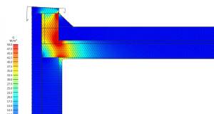
The image below shows a steel column (abutted by the inner leaf of a cavity wall on both sides) penetrating through a floor slab down to a foundation pad. Ignoring other numerous obvious issues with this image, let’s focus on the continuity of the steel down to foundation.
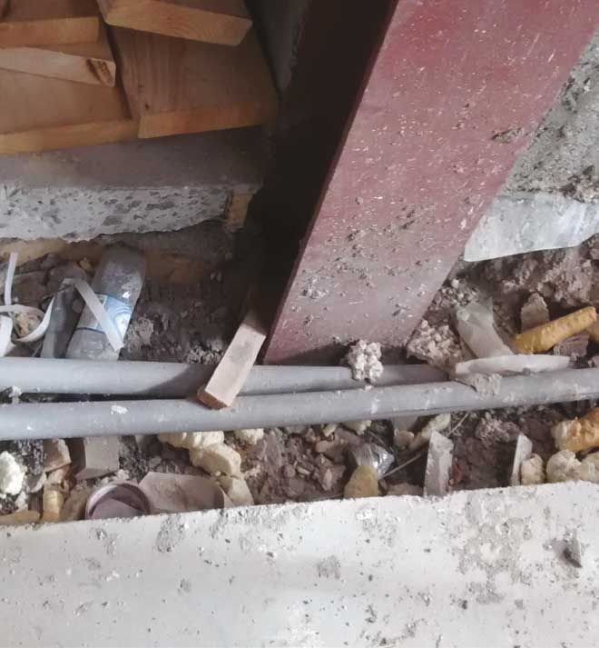
Image showing non-thermally broken, continuous steel to foundation.
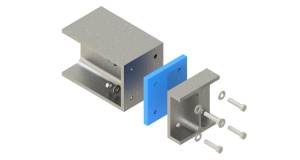
In this case, splitting the steel into two columns and inserting a thermal break, would serve many purposes. Manufacturers such as Armadillo and Farrat have designed thermal breaks for this scenario. As shown on the image, the thermal break itself is quite thin, with thicknesses from 13mm to 50mm available for this product. The compressive strength of the break pad is 290N/mm2, and it has a thermal conductivity of 0.30W/mK.
An illustration of an Armadillo thermal break plate.
The location of the thermal break in the construction is also very important, and this would need to be determined firstly in order to correctly design the steels. Firstly, the thermal break would always be installed in the same line as the insulation of the floor (or other element). But at for example 25mm thickness, with perhaps 150mm thick insulation in the floor, where then does one place it? The reality is that this would need to determined by thermal modelling, so anyone interested in specifying this should firstly approach the supplier for guidance and perhaps project-specific modelling of the detail, or at pre-specification the services of an NSAI-accredited thermal modeller, or a UK competent assessor (as outlined in Part L supplementary guidance documents) should be engaged.
Other considerations must also be borne in mind in locating the break, such as ensuring continuity of DPM / radon barriers in the floor slab without creating tricky unbuildable solutions, and thereby designing in a performance gap in the project.
Other advantages of breaking the steels include the fact that the shorter sections can be installed quite easily during construction of the rising walls and the structural slab poured without having to support the entire portal frame on site. Th e remainder of the frame can then be installed just before installation of the insulation, with access to the bolts still being available at this stage, and with a much neater repair to the DPM. The screed can then be poured around the steels.
These thermal breaks do little as regular insulators, but at specifi c points like the ones discussed here, they pack a serious punch over small areas. Not only will they reduce heat losses through steels, but they can also quite dramatically improve internal surface temperatures, thus reducing risk of mould growth and condensation. Unfortunately, mould growth is still occurring at far too significant a rate in new build construction, when of course there should be none whatsoever. And the harsh reality is that in many cases it has inadvertently been designed-in.
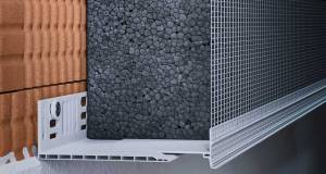
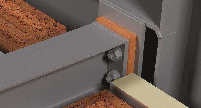
The next type of thermal bridge which demands our attention is the penetration of primary insulation layers in roofs and walls by repeating thermal bridges such as helpinghand brackets, shelf angle brackets, standing seam roof clips and so on. These systems are being increasingly used by architects and designers as the variety of finishes, colours and textures available provide a comprehensive palette that rendered block or brick simply can’t match.
The terracotta rainscreen image shows a typical example of such a system.
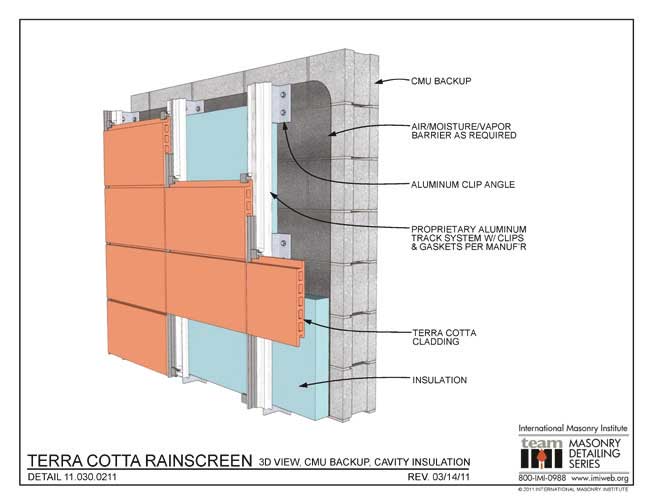
In this example, there is only one layer of insulation on the wall. In all such cases, the helping-hand bracket fully penetrates the entire insulation layer. Now we must consider the fact that the thermal conductivity of the insulation typically used in these systems is about 0.020W/mK, and the thermal conductivity of an aluminium helping-hand bracket is circa 160W/mK. That’s an 8,000-fold increase in thermal conductivity per area. Take a wall area of 600 sqm with brackets installed at a rate of 2.5/sqm, and you have 1,500 brackets. Now we start to get a feel for how significant the additional heat loss can be when such a system is even used on one wall section of a reasonably sized apartment block. This is where the importance of correctly specifying and installing a thermal break to the back plate of the helping hand bracket becomes crucially important.
The systems in these images from Nvelope shows the same bracket and rail system installed here on a cast concrete structure and infill metal stud walling system. In the first image, the bracket penetrates the only insulation there, and will therefore have the more detrimental effect. In the second image, it would be common for insulation to be installed between the metal studs. In this case, the helping-hand bracket doesn’t penetrate the entire thermal envelope, but only the outer insulation layer. So typically, in like-for-like comparison, the additional heat losses due to the bracket in the first image will be greater than in the second. This is despite the bracket, rails and thermal break being identical.

Nvelope bracket & rail systems - one with high risk (left) of thermal bridging and the other (right) with the potential for better performance if the stud is insulated.
So the key point here is that the same system installed in different wall build-ups will perform completely differently. Normally, the suppliers of rainscreen systems are not the suppliers of the wall system, and someone else is supplying the insulation and perhaps someone else the thermal break. So when you as a designer are presented with a table of additional heat loss, or chi-values, or dU (additional penalty values to be added to a U-value) values for a bracket or thermal break, treat these with extreme caution, if not completely ignore them. The odds on that value actually being applicable to your specific wall build-up are as likely as the next White House communications director lasting more than 10 days in the job.
In most examples of such systems that I have calculated, it’s common for a wall U-value to increase somewhere between 30-50% with the inclusion of the rainscreen cladding system. In many cases for example, walls with U-values of say 0.14W/m2K for planar elements will ultimately end up with a U-value of 0.21W/ m2K. This is not an issue when identified at design stage, and the value of 0.21W/m2K is used in the DEAP/SAP/SBEM calculation for the building. Where a ‘default’ and actually inapplicable value for the rainscreen has been used, with a resultant U-value calculation of say 0.17W/m2K being entered into the compliance calculation (or worse yet no addition for the rainscreen system at all), on projects which are already teetering on the edge of demonstrating compliance, let’s just say that the presentation at the next design team meeting never goes down well. Th is is all course completely avoidable.
Concluding comments
There are a few lessons that we still need to learn. Thermal bridge free construction in reality doesn’t exist. Thermal bridges arise mainly from one of two sources, the first being the way we insulate across junctions and around penetrations of the thermal envelope, and the second being literally the way we measure buildings internally in Ireland and the UK. Rather than trying to kid ourselves into thinking we can eliminate thermal bridges, we should set the lower target of trying to treat them as best we can, in the most cost-effective and practical manner, so that what we design can actually be installed without either hanging facades from proverbial sky-hooks or requiring a degree in origami.
A cross-disciplinary approach is required to the specifi cation of thermal breaks. We must comply with building regulations, and in this case the key ones (but not limited to) that come to mind would be structure, fire, acoustics and energy. This would mean a thermal modeller communicating with a structural engineer, fire consultant, acoustic consultant and system supplier, ensuring all parties are satisfied, all coordinated by the architect or project manager to achieve the required result –and all of this happening before the turn of the sod. A bizarre and new concept I know – forgive my sarcasm – but it’s one which might save many an embarrassing project meeting, result in fewer delays on site, reduced costs of remediation during construction, and improve the quality of buildings produced for the end user, which is the least they deserve.